|
Managing Objects using the Cell Library
Using the Cell Library Manager you can insert new objects, delete objects and display existing objects that are stored in the Cell Library. The objects can be used with the following functions:
Cell Generator
Spaced Symbols
Cells from Database
Brush Area
Single Cell
GeoAS Project users have additional access to MapCAD cells by means of the object configurator.
How to create a new cell:
| 1. | Draw the object you want to add to a cell library (you can use any layer including the cosmetic layer). |
| 2. | Select the object and open the cell library manager.
(please note that the selection color will be displayed in the preview window when you add a new cell.) |
| 3. | Optionally you can open another cell library where to store the new cell in. |
| 4. | Enter a name for the new cell. Optionally choose the needed/required settings.
|
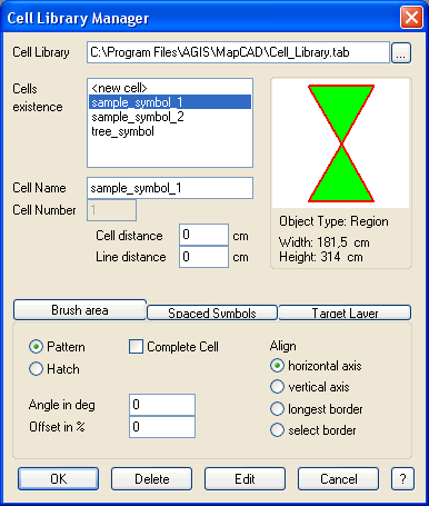
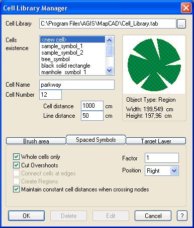
Cell Library:
Select the cell library you wish to add your cell to.
Cells:
The available cells are listed here. If <new cell> is activated, you can name the currently selected object and add it as new cell to the cell library.
Cell Name:
Enter the new cell name or rename an existing cell here.
Cell Number:
Each cell gets an individual identification number, which is displayed here.
Cell Information:
Information about the cell is displayed here:
a) Object Type: Region, Line/Polyline, Point/MultiPoint or Collection
b) Width and Height of the cell
Cell distance and Line distance
The values entered here can be used for the "Cell Generator" "Spaced Symbols" and "Brush Area" functions.
Special settings for the Brush Area function:
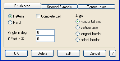
Pattern:
With the „Cell Generator" function a matrix layout of cells is created atop the region object. Overlapping parts are cut off.
Hatch:
Only Line or Polyline objects (horizontal straight lines) or Region objects (x,y axially parallel closed rectangles) can be used for this option.
The lenght of these objects is internally adapted, so that one object is as long as one side of the matrix. The lenght of the objects is therefore not important, as opposed to the width of Region objects. The width determines the width of the Region objects in the hatch.
If the „Hatch" option is selected, a line distance > 0 has to be entered.
Angle in degrees:
This angle is added to the orientation of the selected object.
Offset in %:
This entry determines the offset between objects in adjacent lines.
Complete Cell:
This checkbox determines whether only whole cell objects shall be inserted with the „Brush area" function or if also partyally cut off cell objects will be used.
Align:
This entry determines the orientation of the cells when the „Brush area" function is used.
Special settings for the Spaced Symbols function:
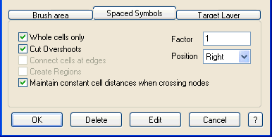
Whole Symbols only:
Only whole symbols are displayed (for example at corners)
Cut Overshoots:
Symbols are extendend into the corners and cut off where the are too long
Connect Symbols at Edges:
Start and end points of the cells are connected if they have the same y coordinate.
Create Regions:
Additionally, a region object is created from the cell objects (only available in combination with Connect Symbols at Edges).
Maintain constant cell distances when crossing nodes:
By default, a cell symbol is placed at the beginning of every segment of a polyline, regardless of the distance to the previous cell symbol. If the original polyline or polygon consists of many relatively short segments, the distances between the spaced cell symbols can look very unregular. For this reason in GeoAS MapCAD 4.6 this function was supplemented with the "maintain constant cell distances when crossing nodes" option. The cell distance is then maintained even when a new polyline segment begins between the cells.
Factor:
Scaling factor for the cells
Position:
Position of the cells relative to the line (Left, Right, Center)
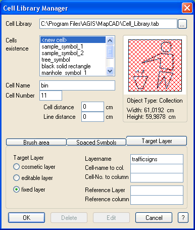
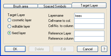
Special settings for the Target Layer presettings
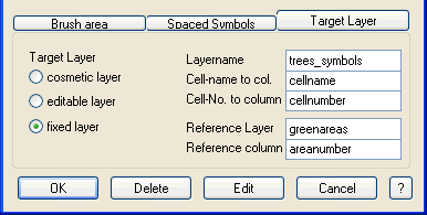
The „Target Layer" tab page contains complete information concerning databases.
Target Layer:
Here, the user can determine, in which layer the cell will be positioned. Under „fixed layer" a specific table can be entered. Die Eingabefelder auf der rechten Dialogseite werden freigeschaltet. Mit Ausnahme des Layernamens sind sämtliche Angaben optional!
If a fixed layer is determined in the cell library, but not open when a cell function is used, or if „editable layer" is chosen and no layer editable, when a cell function is used, the cells are positioned in the cosmetic layer by default.
If cells are used in different layers, the target should set to „editable layer". For cells used for region fill or as spaced symbols by means of the Object Configurator for GeoAS Project Application Modules you should define a fixed target layer.
Layername:
Table name used as fixed layer.
Cell-name to col.:
Enter the column holding the cell’s name.
Cell-No. to column:
Enter the column holding the cell’s number.
Reference Layer/column:
Once set cells can be linked to a reference object via key and the declaration of a reference layer and its reference column. They will be interpreted by the MapCAD routines Single Cell, Spaced Symbols and Brush Area(quod vide).
Use the "OK" Button to save the new or edited cell in the cell.
Use the "Delete" button to delete cells from the library.
Use the "Edit" button to visualize and edit existing cells in a map window.
Use the "Cancel" button to exit the cell library manager withou saving.
 Notes: Notes:
| • | The standard Cell Library name is "Cell_Library.tab". The Cell Library is a regular MapInfo Prof. table and must have the projection Non-Earth (m).
The required table structure for cell libraries is documented in the Table Definition chapter. |
| • | We recommend saving cells in different cell libraries for a structured management of different cell libraries. Besides you can use the standard cell library "Cell_Library" as a template. Open the standard cell library "Cell_Library" with common MapInfo functions and create a new table based on the table structure of the sample cell library. You have access to your "new" cell library with the Cell Library field in your Cell Library manager subsequently. In a multi-user environment we recommend to store the cell library in a dedicated directory. |
| • | A cell object can only be one object. If the cell object consists of several parts, they have to be combined with the <Combine> tool first. |
| • | Keep in mind not to use collections containing symbol objects. These are, like multipoint objects, not scalable, even when used as cells. |
| • | You may delete the sample symbols. Symbols can be added to this cell library. You can save your own symbols in a separate cell library optionally (see above). |
General samples for Cell Manager Configurations:
Cell used as Brush area /Hatch with a predefined angle
Cell used as a symbol in a predefined target layer
Sample 1: including a "bin" symbol to the cell library
| 1. | Digitize the corresponding objects (i.e. into the cosmetic layer). |
| 2. | Select all objects and combine them with the <Objects> <Combine…> function into one object.
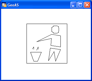 |
| 3. | Select this "bin" object. |
| 4. | Click the "Cell Library Manager" button. |
| 5. | Proceed with the following settings on the dialog mask: |
| - | Choose the cell library you like to add the new object to via browser pad. |
| - | Activate "<new cell>" in the "Cells existence" box and enter the name (bin) into the "Cell Name" field. |
| - | If you intend to run the "Spaced Symbols", "Cell Generator" or "Brush Area" functions with this cell, values for cell and line spaces can be set in the "Cell distance" and "Line distance" fields. For this example this is rather unlikely, thus the boxes remain unfilled. |
| - | Choose the layer you like to paste the cell into as your "Target Layer". The decal information is to be included fixely to the signage table. |
| - | For this example settings of "Brush area" and "Spaced Symbols" are irrelevant.
 |
| 6. | Adopt the cell to the cell library by clicking the "OK" button. |
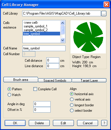
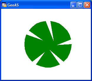
Sample 2: planning an avenue tree planting by means of the cell library.
The tree distance among each other is to be 10m, the distance to the street 50cm. The tree crown diameter is planned to be 1.50m.
| 1. | Digitize a single tree (i.e. within the cosmetic layer). |
| 2. | If the tree consists of several map objects, they have to be selected and combined with the <Objects> <Combine…> function to become one single object.
 |
| 3. | Select the tree object. |
| 4. | Choose the "Cell Library Manager" button. |
| 5. | Proceed with the following settings on the dialog mask: |
| - | Choose the cell library you like to add the new object to via browser pad. |
| - | Activate "<new cell>" in the "Cells existence" box and enter the name (Avenue) for the new cell into the "Cell Name" field. |
| - | Choose 1000cm as cell distance corresponding to 10m between the trees. The line distance will span 50cm according to the distance between the trees and the road surface border. |
| - | The "Brush area" settings are irrelevant for this example. |
| - | As "Target Layer", choose the layer you like to paste the cell into. The avenue is to be included fixely to the tree table. |
| - | You can enter further settings in the "Spaced Symbol" tab page. The cell information field informs about the size of the tree cell object, which is about 2m x 2m. Since the single trees have to be displayed with a crown diameter of 1.50m, the "Factor" of 0.75 will scale down the object. Define a left "Position" to display the spaced symbols left to the line (considering the line direction). Furthermore activate the "Whole cells only" option to avoid displaying incomplete symbols.
 |
| 6. | Adopt the cell to the cell library by clicking the "OK" button. |
The avenue tree cell application is described in the Spaced Symbols chapter.
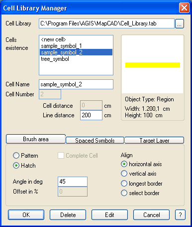
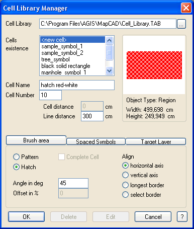
Sample 3: creating red and white region hatchures.
The hatchures have to be displayed in a 45° angle to the horizontal axis with a 3m line distance, whereas the red stripes shall be 2.5m wide.
| 1. | Digitize a rectangle with red fill (i.e. on the cosmetic layer). The rectangle’s height has to match 2.5m, its length is irrelevant.
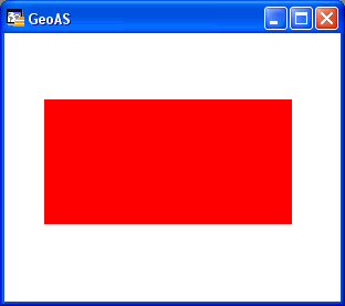 |
| 2. | Select the rectangle object. |
| 3. | Choose the "Cell Library Manager" button. |
| 4. | Proceed with the following settings on the dialog mask: |
| - | Choose the cell library you like to add the new object to via browser pad. |
| - | Activate "<new cell>" in the "Cells existence" box and enter the name (hatchures red-white) for the new cell into the "Cell Name" field. |
| - | Choose 300cm for your line distance as the hatchings repeat each 3m. |
| - | Choose "hatch" for your "Brush area" and an angle of 45°. |
| - | As "Target Layer", choose the layer you like to paste the cell into. Since the hatchings are to be used in different layers, choose the "editable layer" option. |
| - | Choose the "horizontal axis" alignment to align the region fill to the horizontal. |
| - | Settings in the "Spaced Symbols" area are irrelevant for this example.
 |
| 5. | Adopt the cell to the cell library by clicking the "OK" button. |
The red and white region hatchures application is described in the Brush Area chapter.
Supported Objecttypes
Button
|
Objecttyp
|
Processing
|
Annotation
|

|
Point
|
ýý
|
|

|
Line
|
þþ
|
Result objects will be Polyline objects. Polyline objects can be re-converted to Line objects with Convert Polylines to Lines.
|

|
Polyline
|
þþ
|
|

|
Arc
|
þþ
|
Result objects will be Polyline objects.
|

|
Polygon/Region
|
þþ
|
|

|
Ellipse
|
þþ
|
Result objects will be Polygon/Region objects.
|

|
Rectangle
|
þþ
|
Result objects will be Polygon/Region objects.
|

|
Rounded Rectangle
|
ýý
|
|

|
Text
|
ýý
|
|

|
MultiPoint
|
þþ
|
|

|
Collection
|
þþ
|
|
|